Checking a resistor with a multimeter might sound like something only an electrician or electronics engineer would do, but the truth is, anyone can learn how.
Whether your remote control has stopped working, your speaker makes strange noises, or your DIY circuit won’t power on, knowing how to check a resistor with a multimeter can be incredibly useful.
Table of Contents
In this beginner-friendly guide titled “Multimeter How to Check Resistor,” we’ll walk you through everything you need to know in simple, easy-to-understand language. No confusing jargon, no complicated math—just clear instructions for complete beginners.
A resistor is one of the most basic and essential components in any electronic device. Its job is to limit the flow of electricity, ensuring that each part of a circuit gets just the right amount of power.
But just like any other component, resistors can fail over time due to overheating, physical damage, or age. When a resistor goes bad, it can cause anything from minor glitches to complete device failure. That’s why learning how to check a resistor with a multimeter is such a valuable skill.
In this article, “Multimeter How to Check Resistor,” we’ll explain exactly what a resistor is, how it works, and how to use your multimeter to test it safely and accurately. You don’t need any prior experience or special tools—just a little patience and a willingness to learn.
We’ll cover step-by-step instructions for dummies, common types of resistors, and even some tricks for finding faulty resistors directly on an electronic board. So let’s get started and take the mystery out of resistor testing!
What Is a Resistor and Why Check It?
Before diving into how to check a resistor with a multimeter, it’s important to understand what a resistor actually is and why checking it matters. In the simplest terms, a resistor is an electronic component that limits the flow of electricity in a circuit.
Think of it like a traffic light for electrons—it controls how much current flows through different parts of a device to ensure everything functions properly.
Resistors come in many shapes and sizes, and they are found in almost every electronic gadget you own, from smartphones and radios to toys and home appliances.
Resistors play a crucial role in maintaining the stability of electrical circuits. Without them, too much current could flow through sensitive components, causing them to burn out or malfunction.
For example, if a resistor designed to regulate voltage to an LED fails, the LED may flicker, glow too brightly, or stop working altogether.
Similarly, in audio equipment, resistors help control volume levels and signal strength—if one fails, you might hear distorted sound or no sound at all. Understanding these basics helps make sense of why testing a resistor is so important.
There are many practical reasons to measure a resistor with a multimeter. One of the most common uses is diagnosing faulty resistors in broken devices. If a circuit isn’t working as expected, a failed resistor could be the culprit.
By using a multimeter to check its resistance value, you can quickly determine whether it’s still functional or needs replacement. Another valuable application is verifying component specifications, especially when working with salvaged or older parts.
Sometimes, resistors lose their markings over time, making it hard to tell their exact value. Testing them with a multimeter allows you to confirm their behavior before incorporating them into a new circuit.
Additionally, measuring a resistor helps detect open circuits, which occur when a resistor breaks internally and stops conducting electricity completely. A healthy resistor should show a consistent resistance value within its tolerance range.
If the resistance is significantly off or shows an overload symbol (“OL”), the resistor is likely defective and needs replacement.
Some advanced multimeters include additional features like continuity testing, which makes it easier to spot open circuits without needing to read resistance values manually. Even basic tests can give you a good indication of a resistor’s overall condition.
By understanding resistors and how to measure them, you gain a powerful tool for diagnosing and fixing electrical problems.
Whether you’re working on home electronics projects, repairing appliances, or simply trying to understand how circuits work, knowing how to check a resistor gives you valuable insight into the behavior of electrical systems.
The Different Types of Resistors You May Encounter
Resistors come in various types, each designed for specific applications and performance characteristics. Knowing the type of resistor you’re working with helps you interpret your multimeter readings more accurately.
In this section of “Multimeter How to Check Resistor,” we’ll explore the most common resistor types you’ll encounter in everyday electronics, so you know what to expect when testing them.
1. Carbon Composition Resistors
These are among the oldest types of resistors and were widely used in older electronics. They are made by mixing carbon particles with a binding agent and then encasing the mixture in a plastic shell.
Carbon composition resistors are known for their high noise levels and poor stability under heat, making them less commonly used today. However, you’ll still find them in vintage radios, old amplifiers, and early electronic equipment.
These resistors typically have a tolerance range of ±5% to ±20%, meaning their actual resistance can vary quite a bit from the labeled value.
2. Metal Film Resistors
Metal film resistors are one of the most common types found in modern electronics. They offer better precision and stability compared to carbon composition resistors, making them ideal for applications where accuracy is important.
Metal film resistors usually have tight tolerances (±1% or ±2%) and produce less noise, which is why they are often used in audio equipment, computers, and precision measurement devices.
These resistors are typically small, cylindrical in shape, and marked with color bands indicating their resistance value and tolerance.
3. Carbon Film Resistors
Similar to metal film resistors, carbon film resistors consist of a carbon coating on a ceramic base. They are cheaper than metal film resistors but offer slightly lower accuracy and higher noise levels.
These resistors are commonly found in general-purpose electronics and consumer-grade devices.
Their tolerance ranges from ±2% to ±5%, making them suitable for applications where extreme precision isn’t required. Like metal film resistors, they are also marked with color bands for identification.
4. Wirewound Resistors
Wirewound resistors are constructed by winding thin wire around a ceramic core. These resistors are known for their ability to handle high power and precise resistance values, making them popular in power supplies, motor controllers, and industrial equipment.
They are often larger than standard resistors and can sometimes be identified by their cylindrical shape and heat-resistant casing.
While they tend to be more durable than other resistor types, they can still fail due to overheating or physical damage.
5. Surface-Mount Resistors (SMD)
Surface-mount resistors are tiny rectangular components used in modern circuit boards, including smartphones, laptops, and tablets. Unlike traditional leaded resistors, SMD resistors are soldered directly onto the surface of a printed circuit board (PCB) rather than having long leads that go through holes in the board.
These resistors are usually marked with numerical codes instead of color bands, making them trickier to identify without a reference chart. Despite their small size, they function similarly to larger resistors and can be tested using the same techniques described in this guide, “Multimeter How to Check Resistor.”
Each resistor type behaves differently under fault conditions, so identifying the resistor type before testing is crucial. With this knowledge in hand, you’re now ready to prepare your multimeter and begin testing resistors step by step.
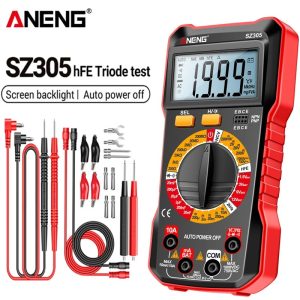
Multimeter offers and deals for resistor checks
Preparing Your Multimeter for Resistor Measurement
Now that you understand the different types of resistors you might encounter, it’s time to prepare your multimeter for the task. Unlike measuring voltage or current, checking a resistor requires a slightly different setup, and it’s crucial to do it correctly to ensure accurate readings.
This section of “Multimeter How to Check Resistor” will guide you through the necessary steps to ensure you’re ready to proceed safely and effectively.
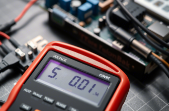
First, locate the dial or selection knob on your multimeter. This is usually found near the center of the device and allows you to choose what type of measurement you want to take—in this case, resistance.
On most digital multimeters, resistance is represented by the Greek letter omega (Ω), which stands for ohms, the unit used to measure resistance. If your multimeter offers multiple resistance ranges, such as 200Ω, 2kΩ, 20kΩ, and so on, start by selecting a mid-range setting like 20kΩ.
If you’re unsure about the expected resistance value, beginning with a mid-range setting ensures that you won’t accidentally overload the meter while still allowing for accurate measurements.
Next, insert the test leads into the correct ports on your multimeter. The black lead should always go into the port labeled “COM,” which stands for common.
This is your reference point. The red lead goes into the port labeled “VΩmA” or something similar, which is designated for measuring voltage, resistance, and small amounts of current.
Some multimeters have a separate high-current port labeled “10A,” but for resistance measurements, you should never use this port. Using the wrong port can result in inaccurate readings or damage to the multimeter, so always double-check the placement of your leads before proceeding.
One important thing to note when measuring a resistor is that many standard multimeters require you to remove the resistor from the circuit before testing.
Unlike voltage or current measurements, where you can often test components in-circuit, resistance measurements can be affected by surrounding components, leading to misleading results. To ensure accuracy, it’s best to desolder or disconnect the resistor entirely before placing it between the multimeter probes.
This ensures that the multimeter is only measuring the resistor’s resistance without interference from other circuit elements. In this moment take look on tutorial for how to check a battery with a multimeter.
Once your multimeter is set up, it’s a good idea to perform a quick calibration step, especially if you’re using an older model. Touch the two probe tips together to create a short circuit.
Since there should be no resistance between the probes when they are touching each other, the multimeter should display a very low resistance reading—ideally close to zero ohms.
If you’re using an analog multimeter, you may need to adjust a small knob on the front of the device to zero out the reading before taking measurements. Digital models typically auto-calibrate, so you can skip this step unless you notice inconsistencies in previous measurements.
With everything set up correctly, you’re now ready to begin measuring the resistor. In the next section of this guide, “Multimeter How to Check Resistor,” we’ll walk you through step-by-step instructions for testing various types of resistors, including through-hole and surface-mount components.
Step-by-Step Instructions: How to Check a Resistor with a Multimeter
With your multimeter properly configured, it’s time to put it to practical use by testing a resistor in a real-world scenario. Check also what is resistor in electronics.
In this part of “Multimeter How to Check Resistor,” we’ll walk through the process step by step, starting with a basic example: measuring the resistance of a through-hole resistor, the type commonly used in breadboards, electronics kits, and older devices.
Begin by locating the resistor you want to test. Through-hole resistors are small, cylindrical components marked with colored bands that indicate their resistance value.
For the most accurate results, it’s recommended to remove the resistor from the circuit before measuring. Testing it while still connected can lead to inaccurate readings due to interference from nearby components.
Once removed, hold the resistor securely in one hand and get your multimeter probes ready in the other.
Set your multimeter to the resistance (Ω) mode. If your meter doesn’t have auto-ranging, select a middle range such as 20kΩ—a safe starting point for many typical resistors.
Touch one probe to each lead of the resistor, making sure there’s firm contact with the metal. The multimeter should then display a numerical reading.
For instance, if you’re measuring a 470Ω resistor, you should see a value near 470 ohms. Due to the resistor’s tolerance—usually ±5% or ±10%, as indicated by the final color band—a 470Ω resistor could measure anywhere between 446Ω and 494Ω and still be within acceptable limits.
If the reading is drastically different (like just a few ohms or an “OL” overload symbol), the resistor may be faulty and should be replaced. Remember, if “OL” appears, your multimeter may be set to too low a range, so increase it and try again.
Now let’s look at another case: measuring a surface-mount resistor directly on a circuit board. These tiny rectangular components are commonly found in modern devices like smartphones and laptops.
Testing them in-circuit is possible, but it can be challenging due to their size and potential interference from nearby components.
First, turn off and disconnect the device from any power source. If the resistor appears burnt or discolored, it may already be compromised. Set your multimeter to the resistance setting (Ω), again starting with a range like 20kΩ. Using fine-tipped probes or tweezers, carefully touch each end of the resistor.
If it’s in good condition, your meter should display a resistance value close to the specified rating. If the reading is way off or shows “OL,” the resistor might be defective. However, for the most reliable measurement, it’s best to desolder and test the resistor separately, especially if other components could be affecting the result.
As you gain experience testing resistors, remember that accuracy depends on consistent technique. Ensure clean, solid contact between the probes and resistor leads, avoid touching the probes with your fingers while measuring, and always verify that your multimeter is set to the correct mode and range.
By following these simple practices, you’ll quickly become confident and capable in testing resistors—just as outlined in this section of “Multimeter How to Check Resistor.”
Understanding and Interpreting Resistor Readings
Once you’ve taken a resistance measurement, the next step is understanding what the numbers on your multimeter mean. In this part of “Multimeter How to Check Resistor,” we’ll break down how to interpret the readings you see on the display and what they signify about the resistor’s condition.
While the exact appearance of the display may vary slightly depending on your multimeter model, most digital versions will show a numerical value followed by a unit of measurement—typically ohms (Ω), kiloohms (kΩ), or megaohms (MΩ).
Let’s start with basic resistance values. Suppose you measured a resistor labeled as 1 kΩ (1,000 ohms) and saw a reading of 0.98 kΩ. This means the resistor is functioning within its expected range, accounting for minor manufacturing tolerances.
Most resistors have a tolerance rating of ±5% or ±10%, meaning their actual resistance can vary slightly from the stated value. If a resistor rated at 470Ω reads 450Ω or 490Ω, it’s still within acceptable limits.
However, if the reading is significantly off—for example, only 200Ω or several thousand ohms—it suggests the resistor is either degraded or burned out and needs replacement.
When testing resistors in real-world scenarios, you may also encounter an “OL” symbol on the display. This stands for “Overload” and appears when the resistance you’re measuring exceeds the selected range on your multimeter.
For instance, if you set your multimeter to 200Ω but attempt to measure a 10kΩ resistor, the display will show “OL” because the resistance is too high for that setting. To resolve this, simply adjust the multimeter’s dial to a higher resistance range and try again.
Some modern multimeters have auto-ranging capabilities, which automatically detect and display the correct resistance without requiring manual adjustments. If your multimeter has this feature, you won’t see an overload warning unless the resistance exceeds the device’s maximum limit, which is typically several megaohms.
It’s also important to note that minor variations in readings are normal and don’t necessarily indicate a problem. Environmental factors, component age, and the quality of your multimeter can all influence the precision of the measurement.
As long as the reading stays within an expected range for the resistor you’re testing, there’s generally nothing to worry about.
With this knowledge, you’ll be better equipped to assess whether the resistance levels you’re measuring are within acceptable limits, allowing you to make informed decisions about your electrical equipment.
Common Faults in Resistors and What They Mean
Knowing how to check a resistor with a multimeter is only half the battle—understanding what the readings mean is equally important. In this section of “Multimeter How to Check Resistor,” we’ll explore the most common faults resistors develop over time and how to identify them using your multimeter.
Recognizing these issues helps you determine whether a resistor is still functional or needs replacement.
1. Open Circuit (No Resistance Reading)
An open circuit means the resistor has completely failed and no longer conducts electricity. When testing with a multimeter in resistance mode, an open resistor will either show an overload symbol (“OL”) or a reading of infinite resistance, indicating that no current can pass through it.
This usually happens when the internal material inside the resistor breaks due to overheating or excessive voltage. Open resistors must be replaced since they prevent the circuit from functioning properly.
2. Short Circuit (Zero Ohms or Extremely Low Resistance)
A shorted resistor creates a direct path for electricity, bypassing its intended function. When tested, a shorted resistor will show very low or zero resistance, regardless of its rated value.
This typically occurs when the resistor experiences a voltage spike or physical damage, causing internal insulation breakdown. Shorted resistors can cause excessive current draw, potentially damaging other components in the circuit.
3. Drift Beyond Tolerance (Out-of-Range Values)
All resistors have a specified tolerance—usually listed as a percentage (±5% or ±10%). If your multimeter shows a resistance value that falls outside this range, the resistor has drifted beyond acceptable limits.
For example, a 1 kΩ resistor with a ±5% tolerance should read between 950Ω and 1,050Ω. If the reading is significantly higher or lower, the resistor is no longer reliable and should be replaced. Drifting resistance values often indicate aging, exposure to heat, or voltage stress.
4. Physical Damage (Burn Marks, Cracks, Discoloration)
While multimeter readings provide electrical insights, visual inspection is just as important. Look for signs of physical damage such as burn marks, cracks, or discoloration on the resistor’s body.
These are strong indicators of overheating or electrical failure. Even if the resistance seems okay, a visibly damaged resistor may be unstable and should be replaced to prevent future failures.
By recognizing these common resistor faults, you’ll be better equipped to diagnose and fix electrical problems. Whether you’re troubleshooting electronics, automotive systems, or household gadgets, knowing how to check a resistor gives you a valuable advantage in diagnosing and resolving electrical issues efficiently.
Step-by-Step: How to Find a Faulty Resistor on an Electronic Board
Now that you know how to test individual resistors, it’s time to apply those skills to real-world situations—like finding a faulty resistor directly on an electronic board. In this section of “Multimeter How to Check Resistor,” we’ll walk you through the process of locating and testing resistors while they are still mounted on a circuit board.
This is especially useful when dealing with complex devices like smartphones, power supplies, or amplifier circuits, where removing every resistor isn’t practical.
Start by visually inspecting the board for obvious signs of resistor failure. Look for burn marks, discoloration, or charring around the resistor body—these are strong indicators of overheating or electrical failure.
If you notice a resistor that looks melted, cracked, or has darkened edges, it’s likely faulty and should be replaced. However, not all resistor failures are visible, so further testing is necessary.
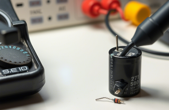
Power down the device and unplug it from any power source. Safety first! Even after disconnecting the device from power, some capacitors on the board may still hold residual charge.
Use an insulated screwdriver to briefly short across large capacitor terminals to discharge them safely before proceeding. This protects both you and your multimeter during testing.
Set your multimeter to the resistance (Ω) mode and choose a mid-range setting like 20kΩ. If your multimeter has an auto-ranging feature, it will automatically adjust to the appropriate scale. Begin by placing the multimeter probes on both sides of the resistor you suspect is faulty.
If the resistor is in a parallel configuration with other components, the reading may not be fully accurate, but it can still give you a good idea of its condition.
Observe the reading. A healthy resistor should display a value close to its rated resistance, considering its tolerance. If the reading is far below or above the expected value, the resistor may be damaged.
If the multimeter shows an “OL” symbol, it indicates an open circuit, meaning the resistor has completely failed and no longer conducts electricity.
If you’re unsure whether the resistor is truly faulty or if surrounding components are affecting the reading, consider desoldering one side of the resistor to isolate it from the rest of the circuit.
This provides a more accurate measurement and confirms whether the resistor is the source of the problem. With these steps, you’ll be well-equipped to find and replace faulty resistors on electronic boards like a pro.
Advanced Tips and Tricks for Detecting Hidden Resistor Problems
While basic resistance measurements can reveal obvious resistor failures, some resistor problems aren’t so easy to spot. In this section of “Multimeter How to Check Resistor,” we’ll share some expert tips and tricks to help you uncover hidden resistor issues that might otherwise go undetected.
These techniques are especially useful when dealing with intermittent faults or resistors that appear fine but are still causing circuit problems.
One highly effective method is performing a temperature test. Overheated resistors can drift out of their normal resistance range, causing erratic behavior in a circuit. To test this, power up the device and let it run for a few minutes.
Then, carefully feel the resistor with your fingers (or use a thermal camera if available). A resistor that feels unusually hot compared to others of the same type might be failing or operating under excessive current.
Be cautious—some resistors naturally get warm, but excessively hot resistors are a red flag.
Another useful trick is measuring resistance while applying gentle pressure. Sometimes, resistors develop internal cracks or weak spots that only show up under stress. Gently press on the resistor with a non-conductive tool like a plastic screwdriver while measuring resistance.
If the reading fluctuates when pressure is applied, it suggests a mechanical failure, and the resistor should be replaced.
Lastly, if you’re working on a board with multiple identical resistors in a circuit, you can compare readings. Measure a known-good resistor and compare it to the suspected faulty one. If one resistor shows a significantly different value despite being the same type, it’s likely defective.
This technique is especially helpful when dealing with surface-mount resistors that lack clear markings.
Using these advanced methods alongside standard resistance checks will improve your ability to diagnose resistor issues quickly and accurately.
Troubleshooting Real-World Resistor Failures
Now that you know how to check a resistor and interpret the readings, let’s explore how to apply this knowledge to real-world scenarios.
In this section of “Multimeter How to Check Resistor,” we’ll walk through examples of resistor-related failures in common electronic devices and how to diagnose and fix them using a multimeter.
Let’s start with a typical situation: a flashlight that refuses to turn on. Before assuming the bulb is dead or the switch is faulty, use your multimeter to check the resistor responsible for limiting current to the LED. Set your multimeter to resistance mode and test the resistor in-circuit.
If the resistor is open (showing an “OL” reading), the LED won’t receive power, explaining why the flashlight doesn’t work. Replacing the resistor with one of the same value should restore functionality.
Another common scenario involves a speaker that produces distorted or no sound at all. Many audio amplifiers use resistors to control signal strength and balance channels. If one channel sounds weaker or cuts in and out, a faulty resistor might be the cause.
Use your multimeter to test resistors in the signal path—especially those near the input or output transistors. If a resistor reads significantly higher or lower than its rated value, replacing it can often restore clear sound.
Household electronics can also benefit from resistor checks. Imagine a smart thermostat that intermittently resets itself. Many thermostats rely on resistors to regulate voltage to sensors and microcontrollers.
A drifting resistor in the power supply or sensor circuit can cause inconsistent operation. By measuring the resistance of key resistors in the power regulation section, you can identify and replace any components that have drifted out of spec.
By systematically checking resistors in different circuits, you can isolate the source of the problem and avoid unnecessary replacements.
Whether you’re troubleshooting electronics, automotive systems, or household gadgets, knowing how to check resistors gives you a valuable advantage in diagnosing and resolving electrical issues efficiently.