You look on guide how to check a battery with multimeter and you have questions now about how to check capacitor. Testing a capacitor with a multimeter might seem tricky at first, but it’s a valuable skill for anyone involved in electronics repair or troubleshooting.
From power supply issues and strange noises in amplifiers to a computer that won’t start, a bad capacitor is often the hidden cause behind these problems.
Table of Contents
In this guide, “Multimeter How to Check Capacitor,” we’ll explain everything you need to know in clear, beginner-friendly language. No technical jargon or complicated equations—just straightforward steps anyone can follow.
A capacitor is a fundamental electronic component that stores and releases electrical energy. It helps stabilize voltage, reduce electrical noise, and manage timing in circuits. However, like any part, capacitors can wear out over time due to factors like heat, aging, or power surges.
When they fail, the result can range from small issues to complete system breakdowns. That’s why learning how to test a capacitor with a multimeter is such a practical and important skill.
What Is a Capacitor and Why Check It?
Before we get into the steps for checking a capacitor with a multimeter, it’s important to understand what a capacitor is and why testing it matters. Check also what is capacitor on electronics.
At its core, a capacitor is a small electronic component that stores and releases electrical energy when needed.
You can think of it like a miniature rechargeable battery—it doesn’t produce power itself, but it holds a charge and delivers it to the circuit when required.
Capacitors are found in nearly every electronic device—from smartphones and computers to TVs, radios, and power supplies. They help regulate voltage, filter electrical noise, and manage timing in digital circuits. Like all electronic components, capacitors can wear out over time.
Excessive heat, moisture, or voltage spikes can cause them to fail—sometimes by leaking, bulging, or simply losing their ability to hold a charge.
When that happens, it can lead to anything from subtle malfunctions to complete device failure.
There are several reasons you might need to test a capacitor with a multimeter. A common one is troubleshooting electronics—particularly power supplies and audio equipment.
For instance, if your charger stops working, your speaker sounds distorted, or your computer won’t boot, a faulty capacitor could be to blame. By testing it with a multimeter, you can quickly determine if the capacitor is still working or if it needs to be replaced.
Testing capacitors is also useful when dealing with older or salvaged parts. Over time, the printed values on capacitors can fade, making it difficult to know their specifications. A multimeter can help verify their performance before you reuse them in a new circuit.
Another key reason to test capacitors is to check for leakage current. This happens when a damaged capacitor fails to properly hold its charge, allowing electricity to slowly escape. A good capacitor should retain its charge with minimal leakage.
While some advanced multimeters offer specific leakage tests, even a basic capacitance reading can tell you a lot about a capacitor’s health.
Understanding how capacitors work—and how to measure them—gives you a major advantage in electronics repair and diagnostics.
Whether you’re tinkering with home projects, fixing appliances, or learning the basics of electronics, being able to test a capacitor can help you solve problems and keep your devices running smoothly.
The Different Types of Capacitors You May Encounter
Capacitors come in many different shapes, sizes, and types, each designed for specific applications. Understanding these differences is essential when learning how to check a capacitor with a multimeter.
In this section of “Multimeter How to Check Capacitor,” we’ll explore the most common capacitor types you’ll encounter in everyday electronics, so you know what to expect when testing them.
1. Electrolytic Capacitors
These are the most commonly found capacitors in power supplies, amplifiers, and other high-voltage circuits. Electrolytic capacitors are usually cylindrical in shape and have polarity markings—one side labeled positive (+) and the other negative (-).
They are known for their large capacitance values, often ranging from 1 µF (microfarad) to thousands of µF.
These capacitors are also prone to failure due to heat and aging, making them one of the most frequently replaced components in electronics repair.
2. Ceramic Capacitors
Ceramic capacitors are small, non-polarized components typically used in high-frequency circuits, filters, and timing applications. They are often found in digital circuits and microcontroller-based devices.
Their capacitance values range from picofarads (pF) to around 1 µF. Unlike electrolytic capacitors, ceramic capacitors do not have polarity, meaning they can be inserted in either direction. While they are more durable than electrolytic capacitors, they can still develop cracks or shorts over time.
3. Film Capacitors
Film capacitors are commonly used in motor controls, audio equipment, and industrial electronics. They are known for their stability and reliability, making them popular in applications where precision is important.
These capacitors are usually encased in plastic and come in various shapes, including rectangular, oval, or cylindrical. They are non-polarized and typically range from 100 pF to several microfarads.
Film capacitors are less likely to fail compared to electrolytic types, but they can still develop issues due to overheating or physical damage.
4. Tantalum Capacitors
Tantalum capacitors are compact, polarized capacitors often used in space-sensitive applications like mobile phones and laptops.
They offer high capacitance in a small package, but they are also sensitive to reverse voltage and overvoltage conditions. Tantalum capacitors typically range from 1 µF to several hundred µF and are marked with a stripe indicating the positive lead.
These capacitors tend to fail catastrophically when subjected to incorrect voltages, often resulting in short circuits or open circuits.
5. Supercapacitors (Ultracapacitors)
Supercapacitors are high-capacity energy storage components capable of holding significantly more charge than standard capacitors.
They are often used in backup power systems, regenerative braking systems in vehicles, and portable electronics. Supercapacitors operate at low voltages but can store large amounts of energy, sometimes in the farad (F) range.
Due to their unique properties, they require special handling and testing techniques, which we’ll cover later in this guide, “Multimeter How to Check Capacitor.”
Each type of capacitor behaves differently under fault conditions, so identifying the capacitor type before testing is crucial. With this knowledge in hand, you’re now ready to prepare your multimeter and begin testing capacitors step by step.
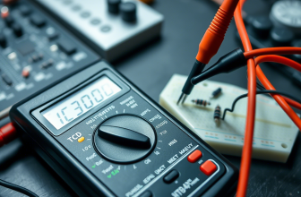
Multimeters deals for good capacitor checks
Preparing Your Multimeter for Capacitor Measurement
Now that you’re familiar with the different types of capacitors, it’s time to get your multimeter ready for testing. Measuring capacitance is a bit different from checking voltage or resistance, so proper setup is key for getting accurate results.
In this part of “Multimeter How to Check Capacitor,” we’ll walk you through the steps needed to prepare your multimeter safely and correctly.
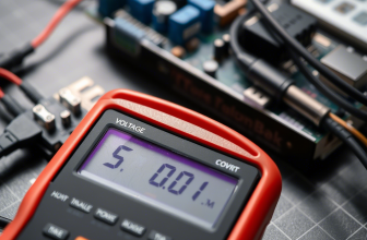
Start by locating the selection dial on your multimeter—usually found in the center. This knob lets you choose the type of measurement you want to perform. For capacitance testing, look for a setting marked with a capital “C” or the symbol for farads (F).
On many digital multimeters, you’ll see several range options like 20nF, 2µF, or 200µF. If your multimeter isn’t auto-ranging, choose the range closest to the expected value of the capacitor.
If you’re unsure, begin with a mid-range setting such as 20µF, and adjust based on your first reading.
Next, connect your test leads properly. The black lead should go into the COM (common) port—this is your ground or reference connection.
The red lead typically goes into the VΩHz port, which is used for voltage, resistance, frequency, and often capacitance. On some models, there may be a separate port specifically for capacitance testing.
Always check your multimeter’s manual to be certain, as incorrect lead placement can give inaccurate readings or potentially damage the device.
A critical step in measuring capacitance is removing the capacitor from the circuit. Unlike voltage or resistance measurements, capacitance readings can be significantly affected by surrounding components.
To get a reliable measurement, you should desolder or disconnect the capacitor from the board before testing it. This ensures you’re only measuring the capacitor itself, not the entire circuit.
Before testing, it’s also important to discharge the capacitor. Some capacitors can retain a charge even after power is removed, which could affect the accuracy of your reading or damage your multimeter.
To safely discharge it, use an insulated screwdriver to touch both leads of the capacitor together briefly. Once it’s discharged, you’re ready to begin testing.
Finally, if you’re using an older multimeter, it may be helpful to perform a quick zeroing or calibration step before testing. This ensures that the meter is operating at its most accurate baseline.
With your multimeter properly configured and the capacitor safely prepared, you’re ready to move on. In the next section of “Multimeter How to Check Capacitor,” we’ll provide step-by-step instructions for testing various types of capacitors.
Step-by-Step Instructions: How to Check a Capacitor with a Multimeter
Now that your multimeter is correctly set up, it’s time to put it to use and test a capacitor in a real-world situation. In this part of “Multimeter How to Check Capacitor,” we’ll guide you step by step through the process using clear and simple instructions.
Let’s begin with a common example: measuring an electrolytic capacitor, which is typically found in power supplies, amplifiers, and other circuits requiring higher capacitance.
Step 1: Identify the Capacitor
Look for the capacitor you want to test. Electrolytic capacitors are usually cylindrical and marked with polarity—one lead is positive (+) and the other negative (–). Before testing, fully discharge the capacitor to avoid damaging your multimeter or getting a false reading.
You can do this by briefly touching both leads with an insulated screwdriver. If you see a small spark, that’s normal—it just means stored charge has been safely released.
Step 2: Set Your Multimeter
Switch your multimeter to capacitance mode, typically marked with a “C” or the farad symbol (F). If your device has multiple ranges, select the one that best matches the capacitor’s rating. For instance, for a 470 µF capacitor, use the 2000 µF range or the closest option available.
Step 3: Take the Measurement
Place the capacitor on a flat, non-conductive surface. Touch the red probe to the positive lead and the black probe to the negative lead. Ensure solid contact with the metal leads. The display should show a numerical value.
A healthy 470 µF capacitor will typically read somewhere between 376 µF and 564 µF, accounting for its ±20% tolerance.
If the multimeter shows a much lower value, or if it displays “OL” (overload), the capacitor may be defective. Try switching to a higher range if “OL” appears, just to be sure.
Example 2: Ceramic Capacitors
Ceramic capacitors are smaller, non-polarized components used in high-frequency or timing circuits. Since they have no polarity, you can connect the probes in either direction.
While they store less charge than electrolytics, it’s still good practice to discharge them.
Set your multimeter to a low capacitance range—commonly in nanofarads (nF) or picofarads (pF)—depending on the expected value. For a 100 nF capacitor, use a range like 200 nF.
Touch both leads with the probes and check the reading. If it’s far below the labeled value or the display shows “OL,” the capacitor might be faulty.
Example 3: Film Capacitors
Film capacitors are found in motors, audio equipment, and industrial electronics. They’re often rectangular or box-shaped and are also non-polarized.
Follow the same process:
- Discharge the capacitor if needed
- Set your multimeter to the correct range
- Place a probe on each terminal
If the measurement is within the expected tolerance, the capacitor is functioning correctly. If the reading is drastically different or the display shows no value, it’s likely defective.
Final Tips for Accurate Readings
- Make sure the probes are making solid contact with the leads
- Avoid touching the metal parts of the probes with your fingers while testing
- Always double-check your multimeter settings before each measurement
With practice and attention to detail, you’ll quickly become confident in checking capacitors using your multimeter. This hands-on skill is essential for diagnosing and repairing a wide range of electronic devices, as outlined in this section of “Multimeter How to Check Capacitor.”
Understanding and Interpreting Capacitor Readings
Once you’ve taken a capacitance measurement, the next step is understanding what the numbers on your multimeter mean.
In this part of “Multimeter How to Check Capacitor,” we’ll break down how to interpret the readings you see on the display and what they signify about the capacitor’s condition.
While the exact appearance of the display may vary slightly depending on your multimeter model, most digital versions will show a numerical value followed by a unit of measurement—typically farads (F), microfarads (µF), nanofarads (nF), or picofarads (pF).
Let’s start with basic capacitance values. Suppose you measured an electrolytic capacitor labeled as 100 µF and saw a reading of 98 µF. This means the capacitor is functioning within its expected range, accounting for minor manufacturing tolerances.
Most capacitors have a tolerance rating of ±20%, meaning their actual capacitance can vary slightly from the stated value. If a capacitor rated at 470 µF reads 400 µF or 520 µF, it’s still within acceptable limits.
However, if the reading is drastically different—for example, 50 µF instead of 470 µF—it suggests the capacitor is damaged or degraded and needs replacement.
When testing ceramic or film capacitors, the expected values are much smaller, often in the nanofarad (nF) or picofarad (pF) range. For instance, if you tested a ceramic capacitor labeled as 10 nF and got a reading of 9.8 nF, that indicates a healthy, functional component.
However, if the reading jumps to several hundred nanofarads or displays an overload symbol (“OL”), it means the capacitor is either shorted or has incorrect internal insulation.
This is particularly useful when troubleshooting timing circuits, oscillators, or filters where precise capacitance values are critical.
When reading capacitance values on a multimeter, you might occasionally see the symbol “OL” on the display. This stands for “Overload” and indicates that the capacitance of the component you’re testing exceeds the range currently selected on your multimeter.
For example, if your meter is set to the 20 µF range and you try to measure a 100 µFcapacitor, the display will show “OL” because the value is too high for that setting.
The solution is simple—just turn the dial to a higher capacitance range and measure again.
Many newer multimeters come with auto-ranging functionality, which automatically selects the correct range based on the component being tested.
With these models, you usually won’t encounter an “OL” warning unless the capacitor’s value is beyond the meter’s maximum measurable limit—often several thousand microfarads.
It’s also worth mentioning that slight fluctuations in readings are completely normal. Factors like ambient temperature, the age of the capacitor, and the accuracy of your multimeter can all affect the result.
As long as the measured value falls within the expected tolerance for that capacitor—typically ±10% or ±20%—there’s no cause for concern.
By understanding what “OL” means and knowing how to interpret slight variations in your readings, you’ll be more confident in evaluating capacitor health and determining whether a component needs replacement.
This insight is a key part of effectively using your multimeter for troubleshooting and maintenance.
Common Faults in Capacitors and What They Mean
Knowing how to check a capacitor with a multimeter is only half the battle—understanding what the readings mean is equally important.
In this section of “Multimeter How to Check Capacitor,” we’ll explore the most common faults capacitors develop over time and how to identify them using your multimeter. Recognizing these issues helps you determine whether a capacitor is still functional or needs replacement.
1. Open Circuit (No Capacitance Reading)
An open circuit means the capacitor is completely dead and no longer able to hold a charge. When testing with a multimeter in capacitance mode, an open capacitor will either show an overload symbol (“OL”) or a reading of zero.
This usually happens when the internal dielectric material breaks down or the capacitor’s leads become disconnected internally. Open capacitors are essentially useless in a circuit and must be replaced.
2. Short Circuit (Low Resistance or Zero Ohms)
A shorted capacitor creates a direct path for electricity, bypassing its intended function. When testing in resistance mode, a shorted capacitor will show very low resistance (close to zero ohms) regardless of the polarity.
This is a sign that the internal insulation has failed, allowing current to flow freely through the capacitor. Shorted capacitors can cause excessive current draw, overheating, and even damage to other components. These must be removed and replaced immediately.
3. Leakage Current (High Resistance but Not Infinite)
Capacitors are supposed to block DC current once fully charged. However, aged or damaged capacitors can develop leakage current, meaning they allow small amounts of electricity to pass through.
When tested in resistance mode, a leaking capacitor will show lower-than-expected resistance, though not a full short. For example, a healthy electrolytic capacitor should show very high resistance (often in the megaohm range) when tested in reverse bias.
If the resistance drops significantly over time or remains low, the capacitor is failing and should be replaced.
4. Swollen or Leaking Electrolytic Capacitors
Physical signs of failure are just as important as electrical tests. Electrolytic capacitors are especially prone to degradation, and one of the most obvious indicators of failure is a bulging top or leaked brownish fluid.
This happens when internal pressure builds up due to overheating or overvoltage. Even if the capacitance reading seems okay, a swollen or leaking capacitor is unreliable and should be replaced to prevent future failures.
5. Incorrect Capacitance Value (Out of Tolerance)
Capacitors have a tolerance range—usually listed as a percentage (±20% for electrolytic capacitors, ±5% for ceramic capacitors).
If your multimeter shows a capacitance value that is far outside this range, the capacitor is no longer performing as expected. This can lead to unstable circuit operation, especially in power supplies, filters, and timing circuits.
Always compare the measured value with the printed rating to determine if the capacitor is still viable.
By recognizing these common capacitor faults, you’ll be better equipped to diagnose and fix electrical issues.
Whether you’re troubleshooting electronics, automotive systems, or household gadgets, knowing how to check a capacitor gives you a valuable advantage in diagnosing and resolving electrical problems efficiently.
Step-by-Step: How to Find a Faulty Capacitor on an Electronic Board
Now that you know how to test individual capacitors, it’s time to apply those skills to real-world situations—like finding a faulty capacitor directly on an electronic board.
In this section of “Multimeter How to Check Capacitor,” we’ll walk you through the process of locating and testing capacitors while they are still mounted on a circuit board.
This is especially useful when dealing with power supplies, motherboards, or audio amplifiers where removing every capacitor isn’t practical.
Start by visually inspecting the board for obvious signs of capacitor failure. Look for bulging tops, leaked fluid, or corrosion—these are strong indicators of a failed electrolytic capacitor.
Swollen or burst capacitors are easy to spot and should be replaced immediately, even if they appear to be within range when tested. However, not all faulty capacitors show visible damage, so further testing is necessary.
Next, power down the device and unplug it from any power source. Safety first! Even after turning off the device, some capacitors—especially large electrolytic ones—can retain a dangerous charge.
Use an insulated screwdriver to briefly short across the capacitor’s terminals to discharge it safely. This ensures that any stored electricity is dissipated, protecting both you and your multimeter during testing.
Set your multimeter to the resistance (Ω) mode. This is the most effective way to check for leakage or shorts in capacitors while they are still soldered to the board. Place the red probe on the positive side of the capacitor (for polarized types like electrolytic or tantalum) and the black probe on the negative side.
For non-polarized capacitors like ceramic or film types, the orientation doesn’t matter—you can test them in either direction.
Observe the resistance reading. A healthy capacitor should initially show a brief dip in resistance as it begins to charge, then slowly climb toward an open circuit (infinite resistance). If the resistance remains low or shows a direct short (0 Ω), the capacitor is likely shorted and needs replacement.
If the resistance is abnormally low but not a full short, it may be leaking current, which can still affect circuit performance.
If your multimeter has a dedicated capacitance measurement mode, you can attempt to measure the capacitor’s capacitance directly. However, keep in mind that surrounding components can skew the reading.
If the value is significantly off from the labeled rating, the capacitor is suspect. If you get an “OL” (overload) symbol, the capacitor may be open and unable to hold a charge.
Remember, in-circuit testing is not always 100% accurate, especially with ceramic or small-value capacitors. If you’re uncertain, it’s best to desolder the capacitor and test it independently for a more reliable result.
With these steps, you’ll be well-equipped to find and replace faulty capacitors on electronic boards like a pro.
Advanced Tips and Tricks for Detecting Hidden Capacitor Problems
While basic capacitance and resistance measurements can reveal obvious capacitor failures, some capacitor problems aren’t so easy to spot. In this section of “Multimeter How to Check Capacitor,” we’ll share some expert tips and tricks to help you uncover hidden capacitor issues that might otherwise go undetected.
These techniques are especially useful when dealing with tricky faults that don’t show up in standard tests but still affect circuit performance.
One highly effective method is measuring Equivalent Series Resistance (ESR). ESR refers to the internal resistance of a capacitor, and while most standard multimeters don’t measure ESR directly, it’s a major factor in capacitor health.
High ESR in an electrolytic capacitor can cause power supply ripple, unstable output, or poor filtering, even if the capacitance value appears normal. To indirectly assess ESR, measure the capacitor’s resistance in series with a known resistor and calculate the drop in performance.
Alternatively, invest in an ESR meter—a specialized tool that provides more accurate results and is invaluable for diagnosing subtle capacitor issues in power supplies and switch-mode circuits.
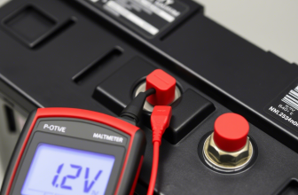
Another useful trick is performing a voltage retention test. Start by charging the capacitor with a safe power supply or battery (never exceed the capacitor’s voltage rating!) and then disconnect it from the power source.
Wait a few minutes and measure the voltage across the capacitor with your multimeter. A healthy capacitor should retain most of its charge for a short period.
If the voltage drops rapidly, it indicates internal leakage or a weak dielectric, signaling that the capacitor should be replaced.
If you’re working with a circuit board and suspect a faulty capacitor but can’t easily remove it, try the freeze spray test. Apply a small amount of freeze spray (used for detecting temperature-sensitive faults) to the capacitor and monitor the circuit’s behavior.
If the device momentarily starts working or changes performance when cooled, it points to a thermal issue in the capacitor or surrounding components.
This method helps pinpoint intermittent failures caused by heat-related stress or internal breakdowns that occur under normal operating temperatures.
Lastly, if you’re dealing with analog circuits or audio equipment, pay attention to audible hum or noise. A failing capacitor in a power supply or audio path can introduce distortion, buzz, or popping sounds.
Swap suspected capacitors with known-good ones to see if the issue improves. This trial-and-error approach can save time when multimeter readings are inconclusive.
By applying these advanced techniques, you’ll be able to catch capacitor issues that might otherwise slip past a standard test.
With consistent practice and exploration, your multimeter—and your eyes and ears—will become indispensable tools in your quest to track down faulty capacitors.
Troubleshooting Real-World Capacitor Failures
Now that you know how to check a capacitor and interpret the readings, let’s explore how to apply this knowledge to real-world scenarios.
In this section of “Multimeter How to Check Capacitor,” we’ll walk through examples of capacitor-related failures in common electronic devices and how to diagnose and fix them using a multimeter.
Let’s start with a typical situation: a desktop computer power supply that intermittently fails to start. Power supplies rely on large electrolytic capacitors to smooth out voltage fluctuations and provide stable power to the system.
Over time, these capacitors can degrade, leading to unstable output voltages and random shutdowns. To test them, first unplug the power supply and open the casing. Discharge any remaining charge in the capacitors by briefly touching both leads together with an insulated screwdriver.
Then, set your multimeter to the capacitance measurement mode and test each capacitor individually. If a capacitor labeled as 470 µF reads significantly lower—say, only 200 µF—it means the capacitor has lost its ability to store charge properly and needs replacement.
Replacing these faulty capacitors can often restore normal operation without needing to replace the entire power supply.
Another common scenario involves a car audio amplifier that produces distorted or crackling sounds. Amplifiers use capacitors to filter out noise and stabilize power delivery to the speakers.
If a capacitor in the power filter circuit fails, it can cause audible distortion or intermittent power loss. To test this, disconnect the amplifier from the power source and locate the large filter capacitors near the power input.
Discharge them carefully, then set your multimeter to capacitance mode and test each capacitor. If the measured value is significantly lower than the rated value printed on the capacitor, it indicates degradation and warrants replacement.
Fixing this issue can dramatically improve sound quality and prevent further damage to the amplifier circuitry.
Household appliances can also benefit from capacitor checks. Imagine a washing machine motor that hums but doesn’t spin. Many single-phase AC motors rely on a start capacitor to provide the initial boost needed for rotation.
If this capacitor fails, the motor may struggle to start or run inefficiently. To test the start capacitor, disconnect the appliance from power and locate the capacitor near the motor housing.
Discharge it carefully, then set your multimeter to capacitance mode and test the component. A healthy motor start capacitor typically has a rating between 5 µF and 100 µF, depending on the motor size.
If the measured capacitance is far below the rated value or shows an open circuit (“OL”), the capacitor is likely faulty and needs replacement. This simple fix can save you from unnecessary motor replacements and expensive repairs.
By systematically checking capacitors at different points in a circuit, you can isolate the source of the problem and avoid unnecessary replacements.
Whether you’re troubleshooting electronics, automotive systems, or household gadgets, knowing how to check capacitors gives you a valuable advantage in diagnosing and resolving electrical issues efficiently.
Final Thoughts: Mastering Capacitor Testing with a Multimeter
Testing capacitors with a multimeter is a valuable skill that enables you to diagnose and repair a wide variety of electronic devices. Whether you’re working on power supplies, audio equipment, or everyday household electronics, capacitors are essential for stable circuit performance.
By learning the methods covered in this guide, “Multimeter How to Check Capacitor,” you’ve taken an important step toward identifying faulty components and making effective, cost-saving repairs.
As you continue your journey into electronics, keep in mind that improvement comes with experience. It’s perfectly normal to feel a bit unsure at first—every skilled technician started the same way.
Take the time to get comfortable with different types of capacitors, experiment with testing techniques, and learn to spot subtle signs of failure.
With consistent practice, your ability to diagnose problems will become quicker and more intuitive.
Whether you’re restoring old gadgets, building a DIY project, or just exploring out of curiosity, the knowledge you’ve gained here will serve you well.
Your multimeter is now a powerful tool in your hands—use it confidently to tackle capacitor-related issues. Stay curious, keep learning, and remember: every successful repair brings you closer to mastering the art of electronics troubleshooting.