Measuring a diode with a multimeter might sound like something only electronics experts do, but the truth is, anyone can learn how or anyone can make it to measure diodes properly.
Whether you’re trying to figure out why your power supply isn’t working properly, your car battery keeps dying, or your DIY circuit keeps failing, knowing how to measure a diode with a multimeter can be incredibly useful.
Table of Contents
In this article titled “Multimeter How to Measure Diode,” we’ll walk you through everything you need to know in simple, easy-to-understand language. No confusing jargon, no complicated math—just clear instructions for complete beginners.
A diode is a basic electronic component that allows electricity to flow in one direction while blocking it in the opposite direction, completely blocks the opposite direction but with some exeptions.
Think of it like a one-way valve for electrical current. Diodes are used in many applications, from converting alternating current (AC) to direct current (DC) to protecting sensitive electronics from voltage spikes.
However, just like any other component, diodes can fail over time due to overheating, excessive current, or physical damage. Measuring a diode helps determine whether it’s functioning correctly or if it needs replacement.
This makes it an invaluable skill for troubleshooting electronics, repairing appliances, or even upgrading old equipment in case of restoration of old electronics boards from 70’s, 80’s and later.
In this guide, “Multimeter How to Measure Diode,” we’ll explain exactly what a diode is, how it works, and how to use your multimeter to test it safely and accurately.
You don’t need any prior experience or special tools—just a little patience and a willingness to learn. We’ll also cover safety tips, common mistakes to avoid, and real-life examples of how to test different types of diodes. So let’s get started and take the mystery out of measuring diodes!
What Is a Diode and Why Measure It?
Before diving into the process of measuring a diode with a multimeter, it’s important to understand what a diode actually is and why checking it matters. In the simplest terms, a diode is an electronic component that allows electricity to flow in only one direction.
Think of it as a one-way gate for electric current—it lets electricity pass through in one direction but blocks it from flowing backward. This property makes diodes essential in many electronic circuits, especially those that convert alternating current (AC) into direct current (DC), regulate voltage, or protect sensitive components from electrical surges.
Diodes come in various types, each designed for specific functions. The most common type is the standard rectifier diode, which is used in power supplies to convert AC into DC.
Another widely used type is the light-emitting diode (LED), which produces light when current flows through it. There are also Zener diodes, which help regulate voltage, and Schottky diodes, which allow faster switching in high-frequency circuits.
Regardless of their purpose, all diodes have two terminals: the anode (positive side) and the cathode (negative side). Understanding these basics helps make sense of why testing a diode is so important.
There are many practical reasons to measure a diode with a multimeter. One of the most common uses is diagnosing faulty diodes in power supplies or automotive systems.
If a power adapter stops working, a car battery keeps draining, or a speaker makes strange noises, a failed diode could be the cause. By using a multimeter to check the diode’s condition, you can quickly determine whether it’s still functioning within its expected range or if it needs replacement.
Another valuable application is verifying component specifications, especially when working with salvaged or older parts. Sometimes, diodes lose their markings over time, making it hard to tell their exact function.
Testing them with a multimeter allows you to confirm their behavior before incorporating them into a new circuit,.
Additionally, measuring a diode helps detect leakage current, which occurs when a diode fails to fully block reverse current. A healthy diode should allow current to flow in only one direction, but a damaged one may let some electricity leak through in the wrong direction.
This leakage can reduce efficiency, generate heat, and potentially cause further damage to the circuit. Some advanced multimeters include a dedicated diode test mode, which provides more accurate results than standard resistance measurements. Even basic tests can give you a good indication of a diode’s overall condition.
By understanding diodes and how to measure them, you gain a powerful tool for diagnosing and fixing electrical problems. Whether you’re working on home electronics projects, repairing appliances, or simply trying to understand how circuits work, knowing how to measure a diode gives you valuable insight into the behavior of electrical systems.
Preparing Your Multimeter for Diode Measurement
Now that you understand what a diode is and why it’s important to measure it, it’s time to prepare your multimeter for the task. Unlike measuring voltage or resistance, measuring a diode requires a slightly different setup, and it’s crucial to do it correctly to ensure accurate readings.
This section of “Multimeter How to Measure Diode” will guide you through the necessary steps to ensure you’re ready to proceed safely and effectively.
First, locate the dial or selection knob on your multimeter. This is usually found near the center of the device and allows you to choose what type of measurement you want to take—in this case, diode testing.
On most digital multimeters that support diode measurement, there is a dedicated setting marked with a symbol that looks like a triangle pointing toward a vertical line, often labeled as “DIODE.”
If your multimeter does not have a dedicated diode test mode, you can still perform a basic diode check using the resistance (Ω) mode, though this method is less precise. For best results, always use the dedicated diode test setting if available.
Next, insert the test leads into the correct ports on your multimeter. When measuring a diode, the black lead should always go into the port labeled “COM,” which stands for common.
This is your reference point. The red lead goes into the port labeled “VΩHz” or something similar, which is designated for measuring voltage, resistance, frequency, and sometimes diode characteristics.
Some multimeters have a separate diode input jack labeled specifically for this function, so always refer to your device’s manual to confirm the proper placement of your leads before proceeding.
Using the wrong port can result in inaccurate readings or damage to the multimeter, so always double-check the setup before taking measurements.
One important thing to note when measuring a diode is that many standard multimeters require you to remove the diode from the circuit before testing.
Unlike voltage or resistance measurements, where you can often test components in-circuit, diode measurements can be affected by surrounding components, leading to misleading results.
To ensure accuracy, it’s best to desolder or disconnect the diode entirely before placing it between the multimeter probes. This ensures that the multimeter is only measuring the diode’s behavior without interference from other circuit elements.
Once your multimeter is set up, it’s a good idea to perform a quick calibration step, especially if you’re using an older model.
Some diodes may retain residual charge even after being disconnected from power, which can interfere with the measurement. Before testing, discharge the diode by briefly touching both leads together with an insulated tool like a screwdriver.
This prevents any stored electricity from affecting the reading and protects both you and the multimeter from potential damage. With everything set up correctly, you’re now ready to begin measuring the diode.
In the next section of this guide, “Multimeter How to Measure Diode,” we’ll walk you through step-by-step instructions for testing various types of diodes.
Step-by-Step Instructions: How to Measure a Diode with a Multimeter
Now that your multimeter is properly set up, it’s time to put it into action and measure a diode in a real-world scenario. This section of “Multimeter How to Measure Diode” will walk you through the process in clear, easy-to-follow steps.
Let’s begin with a simple example: testing a standard rectifier diode commonly found in power supplies. These diodes are designed to allow current to flow in only one direction, making them ideal for demonstrating how diode testing works.
Start by identifying the diode you want to test. Most standard diodes are small cylindrical components with two leads—one labeled as the anode (+) and the other as the cathode (-).
If the markings are unclear, you can often identify the cathode by a stripe or band on one end of the diode. Before taking a measurement, it’s best to remove the diode from the circuit entirely.
This ensures that no other components interfere with the test and gives you the most accurate result. Once the diode is free, hold it in one hand and position the multimeter probes in the other.
Set your multimeter to the diode test mode, typically marked with a symbol that looks like a triangle pointing toward a vertical line. If your multimeter does not have a dedicated diode test setting, switch to the resistance (Ω) mode and select a mid-range setting such as 2kΩ.
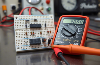
Now, place the red probe on the anode (positive side) of the diode and the black probe on the cathode (negative side). Make sure the probes maintain firm contact with the metal leads of the diode. At this point, the multimeter’s display should light up and show a numerical value.
For a healthy diode in forward bias (current flowing from anode to cathode), you should expect a reading between 0.5V and 0.8V for silicon-based diodes, or 0.2V to 0.3V for Schottky diodes.
This represents the voltage drop across the diode, which is normal for semiconductor materials. If the reading falls within this range, the diode is functioning correctly.
However, if the reading is significantly lower (close to 0V) or shows an overload symbol (“OL”), the diode may be damaged and needs replacement.
Now, let’s reverse the probes to test the diode in reverse bias (current attempting to flow from cathode to anode). Place the red probe on the cathode and the black probe on the anode.
A healthy diode should block current in this direction, so the multimeter should display either an overload symbol (“OL”) or a very high resistance value. If the reading shows a low voltage or allows current to pass in both directions, the diode is likely shorted and must be replaced.
Let’s try another example: testing a light-emitting diode (LED). LEDs function similarly to standard diodes but emit light when current flows through them. Begin by removing the LED from the circuit if possible.
Set your multimeter to the diode test mode and place the red probe on the longer lead (anode) and the black probe on the shorter lead (cathode). A functional LED should show a voltage drop between 1.8V and 3.3V, depending on its color.
Additionally, many LEDs will emit a faint glow during testing, confirming that they are working properly. If the LED shows no voltage drop or fails to light up, it may be defective and needs replacement.
Another common application is testing a Zener diode, often used for voltage regulation. Zener diodes behave like regular diodes in forward bias but allow current to flow in reverse once a specific breakdown voltage is reached.
To test a Zener diode, follow the same steps as with a standard diode in forward bias—you should see a normal voltage drop of around 0.5V to 0.8V. To test the reverse breakdown voltage, you’ll need a safe power supply and a resistor to limit current.
Connect the Zener diode in reverse bias with the power supply and measure the voltage across it. If the reading matches the rated breakdown voltage printed on the diode, it is functioning correctly. If not, the Zener diode may be faulty and needs replacement.
As you practice measuring diodes in different configurations, keep in mind that consistency and proper technique are key to obtaining accurate results.
Ensure that the probes make solid contact with the diode leads, avoid touching exposed metal parts with your hands, and always double-check your multimeter settings before taking a measurement.
By following these simple guidelines, you’ll quickly become comfortable with the process described in this section of “Multimeter How to Measure Diode.”
Understanding and Interpreting Diode Readings
Once you’ve taken a diode measurement, the next step is understanding what the numbers on your multimeter mean. In this part of “Multimeter How to Measure Diode,” we’ll break down how to interpret the readings you see on the display and what they signify about the diode’s condition.
While the exact appearance of the display may vary slightly depending on your multimeter model, most digital versions will show a numerical value followed by a unit of measurement—typically volts (V) or ohms (Ω), depending on the test mode you selected.
Let’s start with the forward bias test, where current flows from the anode to the cathode. If you set your multimeter to the dedicated diode test mode, a healthy silicon-based diode should show a reading between 0.5V and 0.8V.
This represents the voltage drop across the diode, which is normal for semiconductor materials. If you’re testing a Schottky diode, the reading should fall between 0.2V and 0.3V, as these diodes have a lower forward voltage drop.
For light-emitting diodes (LEDs), the expected range varies depending on the color—red LEDs typically show around 1.8V to 2.2V, while blue or white LEDs may read between 3.0V and 3.3V.
If the reading falls within these ranges, the diode is functioning properly. However, if the reading is significantly lower (close to 0V) or shows an overload symbol (“OL”), the diode may be damaged and needs replacement.
When performing the reverse bias test, where current attempts to flow from the cathode to the anode, a healthy diode should block current completely.
In this case, the multimeter should display either an overload symbol (“OL”) or a very high resistance value (often in the megaohm range). This indicates that the diode is successfully preventing current from flowing in the wrong direction.
If the reading shows a low voltage or allows current to pass in both directions, the diode is likely shorted and must be replaced.
If your multimeter does not have a dedicated diode test mode and you’re using the resistance (Ω) setting, the interpretation changes slightly. In forward bias, a good diode should show low resistance, typically in the range of hundreds to thousands of ohms.
In reverse bias, the resistance should be extremely high—ideally showing an “OL” reading, indicating infinite resistance. If the resistance remains low in both directions, the diode is shorted. If it shows high resistance in both directions, the diode is open and non-functional.
It’s also important to note that minor variations in readings are normal and don’t necessarily indicate a problem. Environmental factors, component age, and the quality of your multimeter can all influence the precision of the measurement.
As long as the reading stays within an expected range for the diode you’re testing, there’s generally nothing to worry about. Take a short look on guide about how to measure voltage with multimeter.
With this knowledge, you’ll be better equipped to assess whether the diode levels you’re measuring are within acceptable limits, allowing you to make informed decisions about your electrical equipment.
Common Mistakes and Safety Tips When Measuring Diodes
While measuring a diode with a multimeter is generally safe when done correctly, there are some common mistakes that beginners often make. One of the most frequent errors is attempting to measure a diode while it is still connected to a live circuit.
Unlike voltage or resistance measurements, which can sometimes be taken in-circuit, diode testing should only be performed on components that are completely disconnected from any power source.
Measuring a diode in a live circuit can damage the multimeter, give inaccurate readings, or even pose a risk of electric shock. Always make sure the device or component you’re testing is unplugged and fully discharged before taking any diode measurements.
Another mistake many newcomers make is failing to remove the diode from the circuit before testing it. When a diode remains connected to other components, the multimeter may pick up interference, leading to misleading readings.
For example, if you try to measure a diode while it’s still soldered onto a circuit board, the presence of nearby resistors or capacitors can skew the result. Looking to check capacitor or check resistor, then we have the guides.
To get an accurate measurement, it’s best to desolder or disconnect the diode entirely before testing it. This ensures that the multimeter is only measuring the diode’s behavior without interference from other circuit elements.
Incorrectly selecting the multimeter mode is another issue that can lead to confusion or inaccurate data. Many multimeters offer multiple settings, including voltage, resistance, continuity, and diode test modes.
If you accidentally use the resistance mode instead of the dedicated diode test function, you may misinterpret the results.
While resistance measurements can provide some information, they are not as precise as the dedicated diode test, which applies a known current and measures the resulting voltage drop. To avoid this mistake, always double-check your multimeter’s dial position before starting a test.
Additionally, neglecting to discharge the diode before testing can introduce unwanted variables. Even after disconnecting a device from power, some diodes may retain residual charge, especially if they are part of a power supply or motor control circuit.
Failing to discharge them before measurement can result in inaccurate readings and potential damage to the multimeter. To safely discharge a diode, use an insulated screwdriver to briefly touch both leads together. This allows any stored electricity to dissipate, ensuring a clean and accurate measurement.
Lastly, failing to clean the diode’s leads before testing can introduce unwanted resistance or interference. Dirt, oxidation, or corrosion on the surface of the leads can affect the connection between the diode and the multimeter probes, leading to false readings.
Before placing the probes on a component, gently wipe the leads with a clean cloth or lightly sand them to remove any debris or tarnish. This ensures a solid connection and improves the accuracy of your diode measurements.
By being mindful of these common pitfalls and following basic safety precautions, you can ensure that every diode check you perform is both accurate and secure.
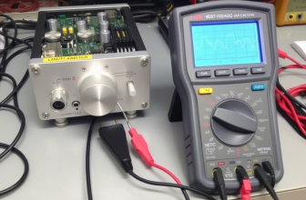
Multimeters deal to measure diodes
Troubleshooting Electrical Problems with Diode Measurements
Now that you know how to measure a diode and interpret the readings, let’s explore how to use this knowledge for troubleshooting common electrical issues. In this section of “Multimeter How to Measure Diode,” we’ll walk through real-world scenarios where measuring diodes can help identify problems in everyday devices and circuits.
Whether you’re dealing with a malfunctioning power supply, a faulty car charging system, or a broken audio amplifier, a multimeter can be a powerful diagnostic tool.
Let’s start with a simple example: a desktop computer power supply that intermittently fails to start. Power supplies rely on rectifier diodes to convert alternating current (AC) into direct current (DC) for stable operation.
Over time, these diodes can degrade due to heat, excessive current, or voltage spikes. To test them, first unplug the power supply and open the casing. Discharge any remaining charge in the capacitors by briefly touching both leads together with an insulated screwdriver.
Then, set your multimeter to the diode test mode and test each diode individually. A healthy diode should show a voltage drop between 0.5V and 0.8V in forward bias and an overload symbol (“OL”) in reverse bias.
If a diode reads abnormally low or conducts in both directions, it is likely faulty and needs replacement. Replacing these faulty diodes can often restore normal operation without needing to replace the entire power supply.
Another common scenario involves a car alternator that fails to charge the battery properly. Alternators use a set of diodes arranged in a bridge configuration to convert the alternating current generated by the alternator into direct current for battery charging.
If one or more diodes fail, the alternator may not produce sufficient power, causing the battery to drain over time. To test the diodes, disconnect the alternator from the vehicle’s electrical system and set your multimeter to diode test mode.
Test each diode in both forward and reverse bias. Check what is reverse bias in electronics and why is important on schematics and circuits.
A healthy diode should show a normal voltage drop in one direction and an overload reading in the other. If any diode shows conduction in both directions or fails to conduct at all, it indicates a fault in the alternator’s diode bridge.
Replacing the faulty diodes or the entire alternator assembly can restore proper charging functionality.
Household electronics can also benefit from diode checks. Imagine a Bluetooth speaker that suddenly stops producing sound. Many audio amplifiers use protection diodes to prevent voltage spikes from damaging sensitive components.
If a diode fails, it can disrupt the signal path or cause erratic behavior. To test this, disconnect the speaker from power and locate the diodes near the amplifier circuitry. Use your multimeter to test each diode individually.
If a diode shows abnormal readings or fails to block current in one direction, it may be responsible for the speaker’s malfunction. Replacing the faulty diode can often restore normal operation without requiring extensive repairs.
By systematically checking diodes at different points in a circuit, you can isolate the source of the problem and avoid unnecessary replacements.
Whether you’re troubleshooting electronics, automotive systems, or household gadgets, knowing how to measure diodes gives you a valuable advantage in diagnosing and resolving electrical issues efficiently.
Expanding Your Multimeter Skills: Beyond Basic Diode Checks
Now that you’ve mastered the fundamentals of measuring diodes with a multimeter, you can begin exploring additional ways to use your tool for more advanced diagnostics.
In this final section of “Multimeter How to Measure Diode,” we’ll introduce a few practical applications that build upon your newfound skills, helping you get the most out of your multimeter.
While diode measurement is an essential starting point, your multimeter can also assist with checking transistor junctions, testing bridge rectifiers, and even identifying damaged components in complex electronics.
One particularly useful skill is learning how to test transistor junctions using the diode test mode. Transistors, especially bipolar junction transistors (BJTs), contain internal diode-like junctions that can be tested similarly to standard diodes.
A functional NPN transistor should show a voltage drop between 0.5V and 0.8V when measuring from the base to the emitter and base to the collector in forward bias, with no conduction in reverse bias.
If any of these junctions show conduction in both directions or no conduction at all, the transistor is likely damaged and needs replacement.
This technique is especially helpful when troubleshooting amplifier circuits, motor controllers, and power supplies where transistors play a critical role in circuit operation.
Testing bridge rectifiers is another valuable application that builds on your diode-measurement knowledge. Bridge rectifiers consist of four diodes arranged in a diamond pattern to convert alternating current (AC) into direct current (DC).
To test a bridge rectifier, set your multimeter to diode test mode and check each of the four internal diodes. Each diode should show a normal forward voltage drop in one direction and an overload symbol (“OL”) in the other.
If any of the diodes conduct in both directions or show no conduction at all, the bridge rectifier is faulty and must be replaced. This technique is especially useful when diagnosing power supply failures in audio amplifiers, battery chargers, and industrial equipment.
Another practical use of diode testing is identifying damaged components in complex electronics. High-end devices like smartphones, laptops, and gaming consoles contain numerous small diodes that regulate power delivery and signal integrity.
When these components fail, the device may exhibit symptoms like random reboots, screen flickering, or charging issues. Using a multimeter with fine-tipped probes, you can inspect and measure individual diodes on a circuit board to identify faulty ones.
This technique is especially useful when repairing water-damaged electronics, as corrosion can degrade diode performance over time.
By expanding your diode-testing techniques beyond basic checks, you gain a more comprehensive toolkit for diagnosing and repairing electrical problems.
Whether you’re verifying transistor health, assessing bridge rectifiers, or tracking down hidden faults in electronics, these additional skills enhance your ability to troubleshoot effectively.
With consistent practice and exploration, your multimeter will become an indispensable companion in both everyday fixes and more complex electronic projects.