Measuring resistance with a multimeter might sound like something only electronics experts do, but the truth is, anyone can learn how.
Whether you’re trying to figure out why your light bulb won’t turn on, your speaker isn’t working, or your DIY circuit isn’t behaving as expected, knowing how to measure resistance with a multimeter can be incredibly useful.
Table of Contents
In this article titled “Multimeter How to Measure Resistance,” we’ll walk you through everything you need to know in simple, easy-to-understand language. No confusing jargon, no complicated math—just clear instructions for complete beginners.
Resistance is one of the fundamental properties of electricity, and it plays a crucial role in how circuits behave. Put simply, resistance determines how easily electricity can flow through a material.
Some materials, like copper wires as google wrotes, have very low resistance, allowing electricity to pass through them effortlessly. Others, like rubber or plastic, have high resistance and block the flow of electricity.
Measuring resistance helps determine whether a component is functioning properly, if a wire is broken, or if there’s an unintended short circuit somewhere in your system.
In this guide, “Multimeter How to Measure Resistance,” we’ll explain exactly what resistance is, how it works, and how to use your multimeter to measure it safely and accurately. You don’t need any prior experience or special tools—just a little patience and a willingness to learn.
We’ll also cover safety tips, common mistakes to avoid, and real-life examples of how to test different components like wires, resistors, switches, and even fuses. So let’s get started and take the mystery out of measuring resistance!
What Is Resistance and Why Measure It?
Before diving into the process of measuring resistance with a multimeter, it’s important to understand what resistance actually is and why checking it matters. In the simplest terms, resistance refers to how much a material or component restricts the flow of electricity.
Think of it like water flowing through a pipe—if the pipe is wide and smooth, water flows easily, but if it’s narrow or has blockages, the flow slows down.
Similarly, in electrical circuits, resistance determines how easily electric current can move through a wire, resistor, or any other electronic component.
Resistance is measured in units called ohms, represented by the Greek letter omega (Ω). The higher the resistance value, the more difficult it is for electricity to pass through. For example, copper wires used in electrical wiring have very low resistance—often less than 1 ohm—which allows electricity to flow freely.
On the other hand, insulating materials like rubber or plastic have extremely high resistance, sometimes in the millions of ohms, which prevents electricity from passing through them.
Understanding resistance helps make sense of how circuits behave and why certain components function the way they do. Take a look about ohms on wikipedia here.
There are many practical reasons to measure resistance in everyday situations. One of the most common uses is checking whether a wire or connection is intact.
If a wire appears undamaged but doesn’t seem to be conducting electricity, measuring its resistance can tell you if it’s broken inside—a problem known as an open circuit. Another common application is testing resistors, which are tiny components designed to limit the amount of current flowing through a circuit.
If a resistor fails or becomes damaged, it may not provide the correct resistance value, causing the circuit to malfunction. By using a multimeter to check its resistance, you can quickly determine whether it needs replacement.
Another valuable use of resistance measurement is verifying continuity, which tells you whether two points in a circuit are connected or not. This is especially helpful when troubleshooting switches, fuses, or printed circuit boards.
If a switch is supposed to close a circuit but doesn’t seem to be working, measuring resistance across its contacts will show whether it’s functioning correctly.
If the resistance is very low (close to zero), the switch is working as intended. If the resistance is extremely high or infinite, the switch is likely faulty and needs repair or replacement.
By understanding resistance and how to measure it, you gain a powerful tool for diagnosing and fixing electrical problems.
Whether you’re working on a home electronics project, repairing a broken appliance, or simply trying to understand how circuits work, knowing how to measure resistance gives you valuable insight into the behavior of electrical systems.
Preparing Your Multimeter for Resistance Measurement
Now that you understand what resistance is and why it’s important to measure it, it’s time to prepare your multimeter for the task. Unlike measuring voltage or current, measuring resistance requires a slightly different setup, and it’s crucial to do it correctly to ensure accurate readings.
This section of “Multimeter How to Measure Resistance” will guide you through the necessary steps to ensure you’re ready to proceed safely and effectively. alternative read the guide about how to check a resistor with multimeter.
First, locate the dial or selection knob on your multimeter. This is usually found near the center of the device and allows you to choose what type of measurement you want to take—in this case, resistance.
On most digital multimeters, the resistance setting is marked with the Greek letter omega (Ω), which stands for ohms, the unit used to measure resistance. Turn the dial to this setting before proceeding.
Some multimeters have multiple resistance ranges, such as 200Ω, 2kΩ, 20kΩ, and so on. If your multimeter does not have an auto-ranging feature, you’ll need to manually select the appropriate range based on what you expect the resistance to be.
If you’re unsure, start with a mid-range setting like 20kΩ and adjust as needed after taking an initial reading.
Next, insert the test leads into the correct ports on your multimeter. When measuring resistance, the black lead should always go into the port labeled “COM,” which stands for common.
This is your reference point. The red lead goes into the port labeled “VΩmA” or something similar, which is designated for measuring voltage, resistance, and small amounts of current.
Some multimeters have a separate high-current port labeled “10A,” but for resistance measurements, you should never use this port.
Using the wrong port can cause inaccurate readings or damage the multimeter, so always verify the placement of your leads before taking any measurements.
Once your multimeter is set up, it’s a good idea to perform a quick calibration step, especially if you’re using an analog multimeter. This involves touching the two probe tips together to create a short circuit.
Since there should be no resistance between the probes when they are touching each other, the multimeter should display a value close to zero ohms.
If you’re using a digital multimeter, this step isn’t strictly necessary because modern models automatically account for internal resistance, but it can still be a helpful way to confirm that your meter is functioning properly.
If you’re using an older analog model, you may need to adjust a small knob on the front of the device to zero out the reading before taking measurements.
With everything set up correctly, you’re now ready to begin measuring resistance. In the next section of this guide, “Multimeter How to Measure Resistance,” we’ll walk you through step-by-step instructions for testing various components like wires, resistors, switches, and fuses.
By following these simple guidelines, you’ll quickly become comfortable with the process and be able to diagnose electrical issues with confidence.
Multimeter deals and offers
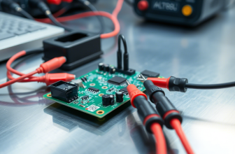
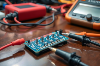
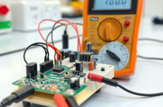
Step-by-Step Instructions: How to Measure Resistance with a Multimeter
Now that your multimeter is properly set up, it’s time to put it into action and measure resistance in a real-world scenario. This section of “Multimeter How to Measure Resistance” will walk you through the process in clear, easy-to-follow steps.
Let’s begin with a simple example: checking the resistance of a basic resistor. Resistors are commonly used in electronic circuits to control the flow of electricity, and knowing how to measure their resistance helps determine if they’re functioning correctly.
Start by identifying the resistor you want to test. Most resistors are small cylindrical components with colored bands indicating their resistance value. Before taking a measurement, it’s best to remove the resistor from the circuit entirely.
This ensures that no other components interfere with the reading and gives you the most accurate result. Once the resistor is free, hold it in one hand and position the multimeter probes in the other.
Touch the red probe to one end of the resistor and the black probe to the other end. Make sure the probes maintain firm contact with the metal leads of the resistor. At this point, the multimeter’s display should light up and show a numerical value.
For example, if you’re testing a resistor labeled as 1 kiloohm (1kΩ), you should expect a reading close to 1,000 ohms.
However, due to manufacturing tolerances, slight variations are normal—most resistors have a tolerance range of ±5%, meaning a 1kΩ resistor could read anywhere between 950Ω and 1,050Ω and still be considered within acceptable limits.
If the reading is significantly off, such as showing only a few ohms or an overload symbol (usually “OL”), the resistor may be damaged and needs replacement. Keep in mind that some multimeters require manual range selection, so if your reading shows “OL,” try switching to a higher resistance range and test again.
Let’s try another example: checking the resistance of a wire or cable. Wires are supposed to have very low resistance since they allow electricity to flow easily.
To test a piece of wire, disconnect it from any power source and place the red probe at one end and the black probe at the opposite end.
If the wire is intact, the multimeter should show a very low resistance value—typically less than 1Ω. If the resistance is extremely high or shows “OL,” the wire is likely broken internally, creating an open circuit.
This method works well for checking headphone cables, extension cords, or any other wiring where a break might be hidden beneath the insulation.
Another common application is testing a switch. Switches control whether a circuit is open or closed, and measuring resistance helps determine if they’re functioning correctly.
With the switch disconnected from power, place one probe on each terminal of the switch. If the switch is in the “on” position, the resistance should be very low—ideally close to zero.
If the resistance remains high regardless of the switch position, it means the internal contacts are faulty and the switch needs replacement.
As you practice measuring resistance in different components, keep in mind that consistency and proper technique are key to obtaining accurate results.
Ensure that the probes make solid contact with the test points, avoid touching exposed metal parts with your hands, and always double-check your multimeter settings before taking a measurement.
By following these simple guidelines, you’ll quickly become comfortable with the process described in this section of “Multimeter How to Measure Resistance.”
Understanding and Interpreting Resistance Readings
Once you’ve taken a resistance measurement, the next step is understanding what the numbers on your multimeter mean.
In this part of “Multimeter How to Measure Resistance,” we’ll break down how to interpret the readings you see on the display and what they signify about the component or circuit you’re testing.
While the exact appearance of the display may vary slightly depending on your multimeter model, most digital versions will show a numerical value followed by a unit of measurement—typically ohms (Ω), kiloohms (kΩ), or megaohms (MΩ).
Let’s start with basic resistance values. Suppose you measured a standard resistor labeled as 470Ω and saw a reading of 468Ω.
This means the resistor is functioning within its expected range, accounting for minor manufacturing tolerances. Most resistors have a tolerance rating of ±5% or ±10%, meaning their actual resistance can vary slightly from the stated value.
If a resistor rated at 1kΩ (1,000Ω) reads 970Ω or 1,030Ω, it’s still within acceptable limits. However, if the reading is drastically different—for example, 200Ω instead of 1kΩ—it suggests the resistor is damaged or incorrect for the circuit.
When testing wires or cables, the expected resistance should be very low, ideally close to zero. If you tested a length of copper wire and got a reading of 0.5Ω, that indicates a healthy, unbroken conductor.
However, if the reading jumps to several hundred ohms or displays an overload symbol (“OL”), it means the wire is broken somewhere inside, preventing electricity from flowing properly.
This is particularly useful when troubleshooting headphones, power cords, or any wiring where physical damage isn’t immediately visible.
Testing switches follows a similar logic. A functional switch should show very low resistance when turned on and infinite resistance when turned off.
For instance, if you placed the multimeter probes on either side of a toggle switch and got a reading of nearly 0Ω while the switch was engaged, that confirms it’s working correctly.
However, if the resistance remains high regardless of the switch position, it indicates a failure in the internal contacts, requiring replacement.
One thing you might encounter when interpreting resistance readings is an “OL” symbol on the display. This stands for “Overload” and appears when the resistance you’re measuring exceeds the selected range on your multimeter.
For example, if you set your multimeter to 200Ω but try to measure a 1kΩ resistor, the display will show “OL” because the resistance is too high for that setting. To resolve this, simply adjust the multimeter’s dial to a higher resistance range and try again.
Some modern multimeters have auto-ranging capabilities, which automatically detect and display the correct resistance without requiring manual adjustments.
If your multimeter has this feature, you won’t see an overload warning unless the resistance exceeds the device’s maximum limit, which is typically several megaohms.
It’s also important to note that minor variations in readings are normal and don’t necessarily indicate a problem. Environmental factors, component age, and the quality of your multimeter can all influence the precision of the measurement.
As long as the reading stays within an expected range for the component or circuit you’re testing, there’s generally nothing to worry about.
With this knowledge, you’ll be better equipped to assess whether the resistance levels you’re measuring are within acceptable limits, allowing you to make informed decisions about your electrical equipment.
Common Mistakes and Safety Tips When Measuring Resistance
While measuring resistance with a multimeter is generally safe when done correctly, there are some common mistakes that beginners often make. One of the most frequent errors is attempting to measure resistance in a live circuit.
Unlike voltage measurements, which can be taken while a circuit is powered, resistance measurements should only be performed on components that are completely disconnected from any power source.
Measuring resistance in a live circuit can damage the multimeter, give inaccurate readings, or even pose a risk of electric shock. Always make sure the device or component you’re testing is unplugged and fully discharged before taking any resistance measurements.
Another mistake many newcomers make is failing to remove the component from the circuit before testing it.
When a resistor, capacitor, or wire remains connected to other components, the multimeter may pick up additional resistance from parallel paths, leading to misleading readings.
For example, if you try to measure a resistor while it’s still soldered onto a circuit board, the presence of nearby components can skew the result. To get an accurate measurement, it’s best to desolder or disconnect the component entirely before testing it.
This ensures that the multimeter is only measuring the resistance of the specific part you’re interested in.
Incorrectly selecting the resistance range is another issue that can lead to confusion or inaccurate data. Many multimeters offer multiple resistance settings, such as 200Ω, 2kΩ, 20kΩ, and so on.
If you set the multimeter to a range that is too low for the component being tested, the display may show an overload symbol (“OL”) instead of the actual resistance value.
Conversely, if you select a range that is too high, the reading might lack precision—for instance, a 470Ω resistor measured on a 200kΩ scale may appear as 0.00kΩ, making it hard to distinguish between a good and faulty component. To avoid this, start with a mid-range setting like 20kΩ and adjust accordingly based on the initial reading.
Additionally, failing to check for continuity before measuring resistance can lead to unnecessary frustration. Continuity testing is a quick way to determine if there is a complete path for electricity to flow between two points in a circuit.
If you suspect a broken wire or a faulty switch, performing a continuity test first can save time and effort. If the multimeter beeps when the probes are touched to both ends of the component, it means there is a continuous connection.
If there’s no beep, the component may be damaged or disconnected, and further resistance measurements can help pinpoint the issue.
Lastly, neglecting to clean the component’s contacts before testing can introduce unwanted resistance. Dirt, oxidation, or corrosion on the surface of wires, connectors, or terminals can interfere with the measurement, leading to false readings.
Before placing the probes on a component, gently wipe the contact points with a clean cloth or lightly sand them to remove any debris or tarnish. This ensures a solid connection and improves the accuracy of your resistance measurements.
By being mindful of these common pitfalls and following basic safety precautions, you can ensure that every resistance check you perform is both accurate and secure.
Troubleshooting Electrical Problems with Resistance Measurements
Now that you know how to measure resistance and interpret the readings, let’s explore how to use this knowledge for troubleshooting common electrical issues.
In this section of “Multimeter How to Measure Resistance,” we’ll walk through real-world scenarios where measuring resistance can help identify problems in everyday devices and circuits.
Whether you’re dealing with a malfunctioning appliance, a broken wire, or a faulty switch, a multimeter can be a powerful diagnostic tool.
Let’s start with a simple example: a lamp that refuses to turn on. Before assuming the bulb is burned out or the switch is faulty, use your multimeter to check the resistance of the components involved.
Begin by removing the light bulb and setting your multimeter to the resistance (Ω) mode. Place one probe on the metal base of the socket and the other on the threaded side. If the reading is close to zero ohms, the socket is functioning properly.
If the resistance is extremely high or shows an overload symbol (“OL”), there may be a break in the wiring or a faulty connection inside the lamp. Next, test the switch by placing the probes on either side of the switch contacts.
If the resistance remains high regardless of the switch position, it means the internal contacts are worn out or damaged and need replacement.
Another common scenario involves a pair of headphones that only produce sound in one ear. Instead of immediately replacing them, grab your multimeter and test the resistance of the audio cable.
Set your multimeter to the lowest resistance setting and place the probes on the corresponding pins of the headphone jack—one on the tip (left channel), one on the ring (right channel), and one on the sleeve (ground).
A normal reading should be very low—less than 1Ω—indicating a continuous connection. If one side shows significantly higher resistance or no connection at all, it means the internal wiring is broken, and the headphones need repair or replacement.
This same approach applies to speaker cables, charging cords, and other wired accessories where signal transmission is critical.
Household appliances can also benefit from resistance checks. Imagine a toaster that suddenly stops heating. Instead of disassembling the entire unit, use your multimeter to test the resistance of the heating element.
Disconnect the toaster from power and remove the outer casing to access the element. Place the probes on the two terminals of the heating coil. A healthy heating element typically has a resistance between 10Ω and 30Ω, depending on the model.
If the resistance is extremely high or shows an open circuit (“OL”), the heating element is likely burned out and needs replacement. This same method applies to electric kettles, space heaters, and other appliances that rely on resistive heating elements to function.
By systematically checking resistance at different points in a circuit, you can isolate the source of the problem and avoid unnecessary replacements.
Whether you’re troubleshooting electronics, automotive systems, or household gadgets, knowing how to measure resistance gives you a valuable advantage in diagnosing and resolving electrical issues efficiently.
Expanding Your Multimeter Skills: Beyond Basic Resistance Checks
Now that you’ve mastered the fundamentals of measuring resistance with a multimeter, you can begin exploring additional ways to use your tool for more advanced diagnostics.
In this final section of “Multimeter How to Measure Resistance,” we’ll introduce a few practical applications that build upon your newfound skills, helping you get the most out of your multimeter.
While resistance measurement is an essential starting point, your multimeter can also assist with checking motor windings, testing thermistors, and even identifying moisture damage in electronics.
One particularly useful skill is learning how to test motor windings for faults. Electric motors contain coils of wire that generate magnetic fields to produce motion. Over time, these windings can develop shorts, opens, or degraded insulation, leading to motor failure.
To test a motor winding, set your multimeter to the resistance (Ω) mode and place the probes on the motor’s terminals. A healthy motor should show a low resistance reading—typically between 1Ω and 30Ω, depending on the motor’s design.
If the resistance is extremely high or shows an open circuit (“OL”), the winding is likely broken and the motor needs repair or replacement. Additionally, comparing the resistance between multiple windings in a three-phase motor can help identify imbalances that may indicate internal damage.
Testing thermistors is another valuable application that builds on your resistance-measurement knowledge. Thermistors are temperature-sensitive resistors commonly used in thermostats, refrigerators, and 3D printers to monitor heat levels.
Their resistance changes predictably with temperature, making them useful for precise thermal control. To test a thermistor, measure its resistance at room temperature and compare it to the manufacturer’s specifications.
Then, expose it to a controlled heat source (such as hot water) and observe how the resistance changes. If the resistance increases or decreases as expected with temperature variation, the thermistor is functioning properly.
If the resistance remains constant or fluctuates unpredictably, the sensor may be faulty and require replacement.
Another practical use of resistance measurement is identifying moisture damage in electronics. Water or humidity exposure can cause corrosion and unintended conductivity between circuit components, leading to short circuits and malfunctions.
To check for moisture-related issues, set your multimeter to a high resistance range (such as 200MΩ) and test the resistance between different sections of the circuit board.
Healthy, dry components should show very high resistance (in the megaohm range), while wet or corroded areas will exhibit significantly lower resistance.
This technique is especially useful when troubleshooting water-damaged smartphones, laptops, or outdoor electronics that have been exposed to rain or condensation.
By expanding your resistance-testing techniques beyond basic checks, you gain a more comprehensive toolkit for diagnosing and repairing electrical problems.
Whether you’re verifying motor health, assessing temperature sensors, or tracking down moisture damage, these additional skills enhance your ability to troubleshoot effectively.
With consistent practice and exploration, your multimeter will become an indispensable companion in both everyday fixes and more complex electronic projects.